Maintenance Information for the Yamaha Riva 180
Riva 180/200 engine removal procedure
With practice the engine can be removed in less than 15 minutes. When working on the carb, I find it way easier to remove the engine than to try and work on it in place.
Place the scoot on its centerstand.
Wiring
Disconnect the wiring connections under the seat (RH side) (alternator, thermoswitch, thermosensor, pickup, fan, oil pressure sensor). Disconnect the battery ground cable (either from the battery or from near the starter where the other end is fastened) and the positive lead to the starter (10mm nut). Disconnect the wiring connections to the solenoids and remove the solenoids from the frame (leave the hoses connected)
Rear brake cable
Unscrew the wing nut on the rear brake cable. Back out the 10mm bolt on the rear brake hub (you don't have to remove it entirely), which has a clamp to hold the rear brake cable. Unscrew the two #3 phillips screws that hold the air box (bottom of air box, attached to the belt case cover). Unbolt the clamp on the belt case cover that is holding the brake cable (5mm allen bolt). Raise up the air box and gently pull the rear brake cable free and tie it up out of the way (I put it on the gas tank).
Petcock connections
Disconnect the petcock connections (I do usually it at the petcock) for the fuel line and the vacuum line.
Hoses
Disconect the hose running to the charcol canister (California models, if so equipped). This is the only hose you need to disconnect. It is easiest to disconnect it at the canister.
Other Cables
Disconnect the throttle cable and the spark plug lead from the spark plug.
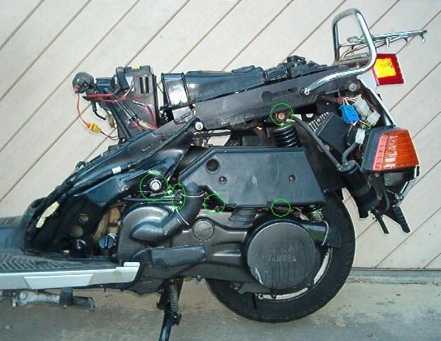
Fasteners
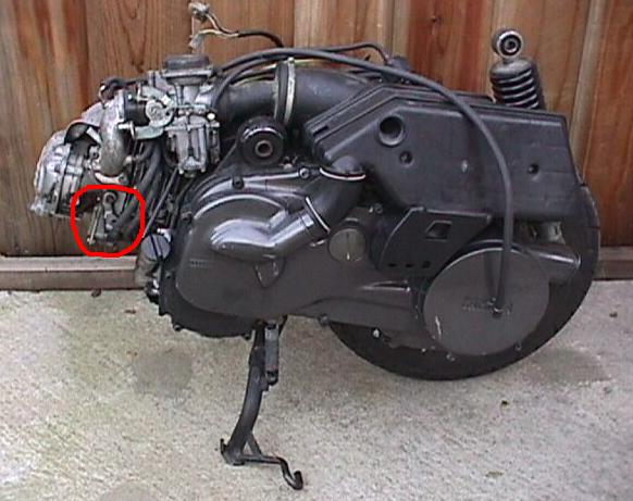
Place a piece of 2 X 4 under the rear wheel (or just support the rear wheel by hand). Remove the 17mm bolt at the top of the shock. Remove the 19mm and 17mm bolts at the front of the engine. Extract the bolt (it is long - it goes all the way through the frame). These are the *only* two mechanical supports for the engine.
Lift the scooter off the engine
Hold the LH grip and place your right hand under the rear fender. Pick up the scooter by the rear fender (it's light without the engine) and lift it off the engine. Place the scooter on a milk crate. The engine will stay nicely on the centerstand.
Now, it's incredibly easy to work on the engine! The engine/rear wheel/carb/ air box are still all together.
Note that for re-install I usually remove the passenger pegs so I can squeeze the engine in a little easier. To do this remove the 10mm floor bolt nearest the passenger pegs on each side. Gently lift up the floorboard and unscrew the two 12mm bolts holding the passenger pegs. Also, you have to be a little careful fitting the rear fender around the air box. Take your time.
I use a 18 Volt cordless impact wrench, which makes this job way easier. It's a great tool for disassembly. You have to be careful when using it for reassembly because it has a lot of power. I tighten everything by hand for the final tightening.
Carb hose routing
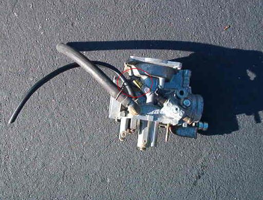
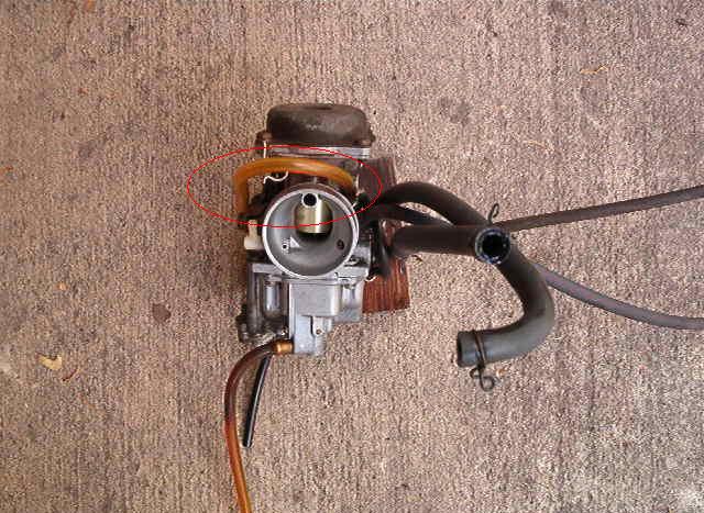
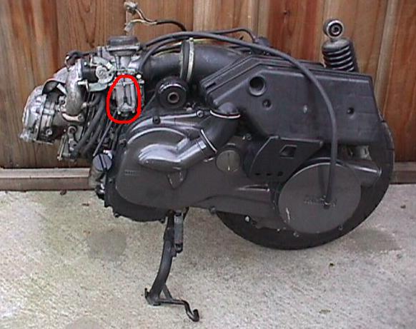
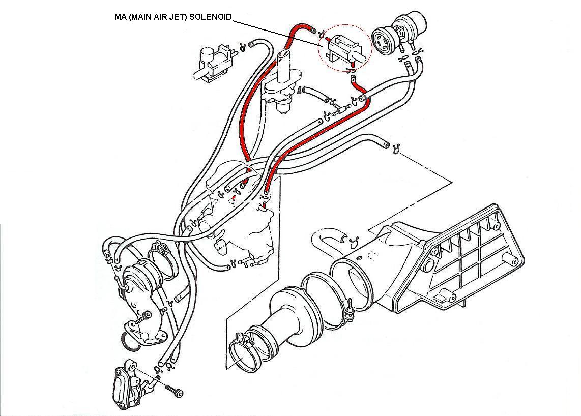
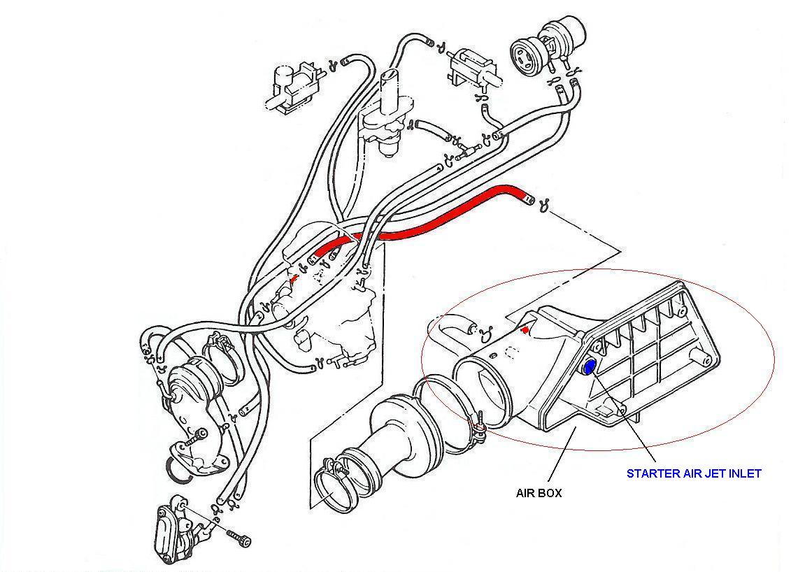
Where do all of those stinkin' hoses go? See the following section for routing diagrams. Here are 3 pictures that show the routing of the hose to the main air jet:Here is the bare nipple on the carb body
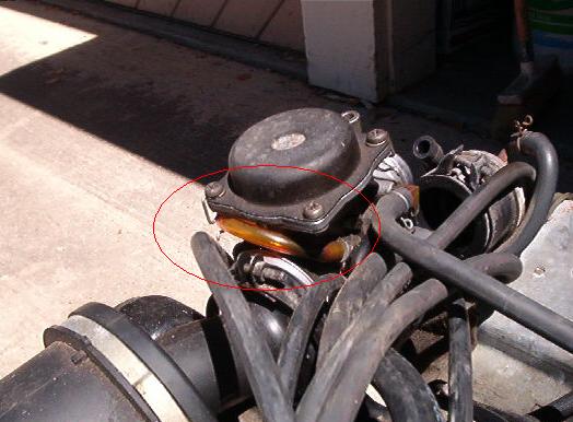
View from the back of the bare carb You can also see the float bowl drain tube and the vent tube for the starting jet
View from the back of the installed carb
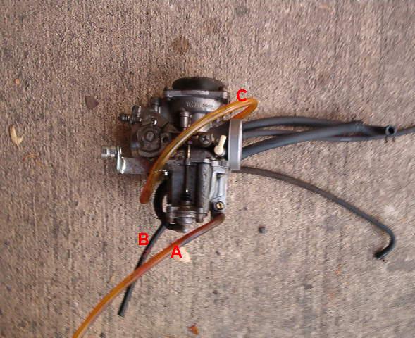
Left hand view, showing the 3 tubes that are vented to the atmosphere:
The clear hose (A) at the bottom is the carb drain hose
The skinny black hose (B) is for the starting circuit.
Inside this hose is a tiny hole for the starting air jet (SAJ2) noted below in the Starting enrichener circuit description.
The clear hose (C) at the top is the main jet vent hose
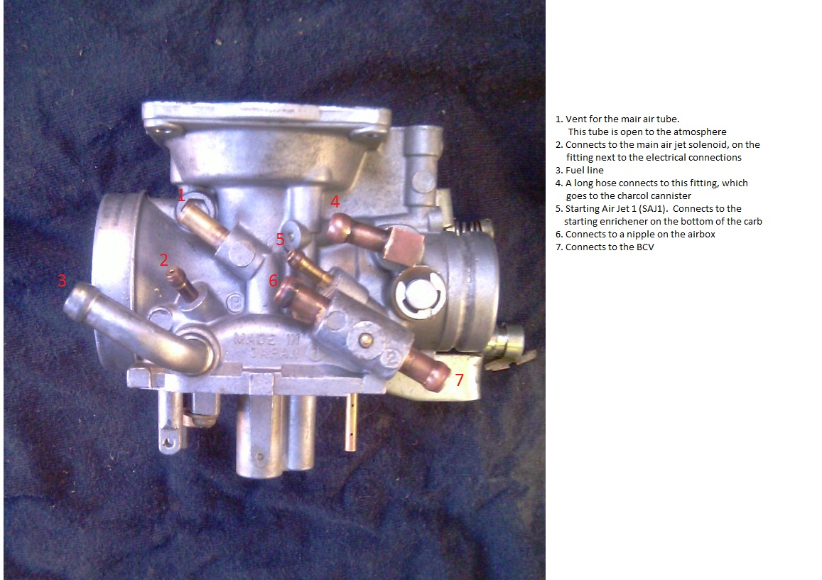
View from the right side of the carb, including labels for each nipple
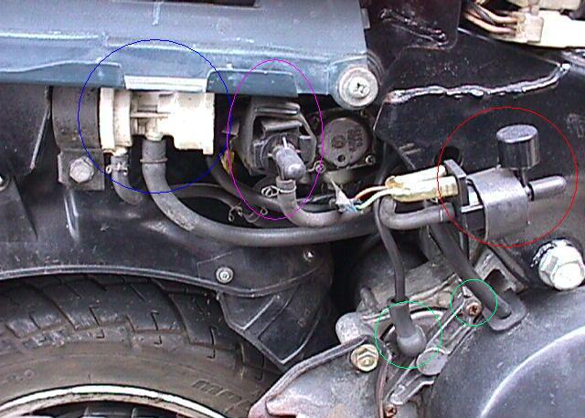
| Components of the carb circuit in general and the starting circuit | I'll have better pics some day... |
|---|---|
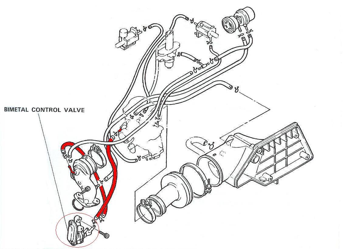
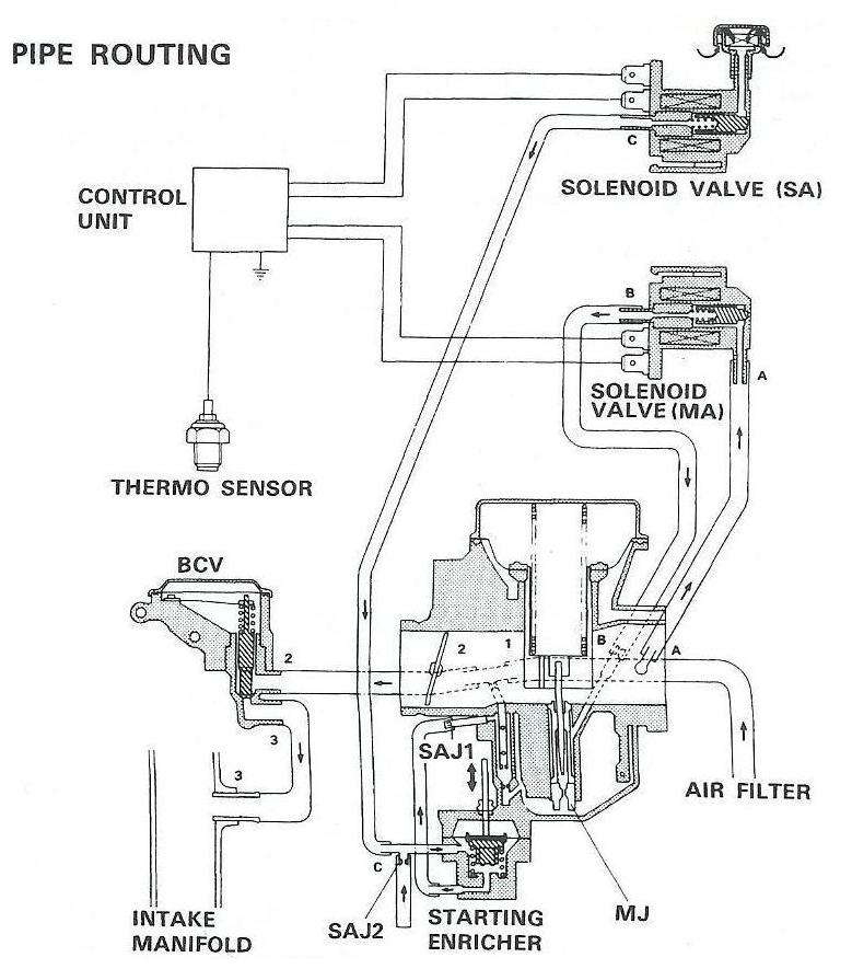
| BCV The bi-metal control valve is fully open at -43 degrees F and fully closed at +130 degrees F. It's actually a simple device. The main functioning piece is a strip dissimilar of metals joined together. The metals have different rates of expansion as temperature rises. This causes the strip to bend slightly, which moves a plunger to move back and forth. The BCV controls air flow through the starting enrichener, so it is needed for cold starts. One tube goes to the carb and the other tube goes into the intake manifold. You can bypass it, but your mixture will be over-rich at low RPMs as the scooter warms up. BCV hose routing diagram. |
 |
| Starting solenoid
(denoted SA in the service manual) Both solenoids are controled by the black box (under the front fender) in the starting circuit. The starting solenoid is the one with only one outlet tube, and it connects to the bottom of the carb. During cold starts (below 68 degrees F), both solenoids should be closed. When you turn the key on a cold scooter, you'll hear a click at the solenoids as 12V is applied to them. This closes them. The SA solenoid draws air from the atmosphere into the starting circuit. Because it's closed on a cold engine, air cannot be drawn in and the starting mixture is rich. As the scooter warms up (around 68 degrees F), the solenoid will open, leaning out the starting mixture. SA hose routing diagram. |
 |
| Main air solenoid (denoted MA in the service manual). This guy is connected from one side of the carb to the other side. Is is closed on a cold scooter (below 68 dergees F), and it opens up at around 104 degrees F. It is not used in starting. It is used to control air flow for the main jet. MA hose routing diagram. |
 |
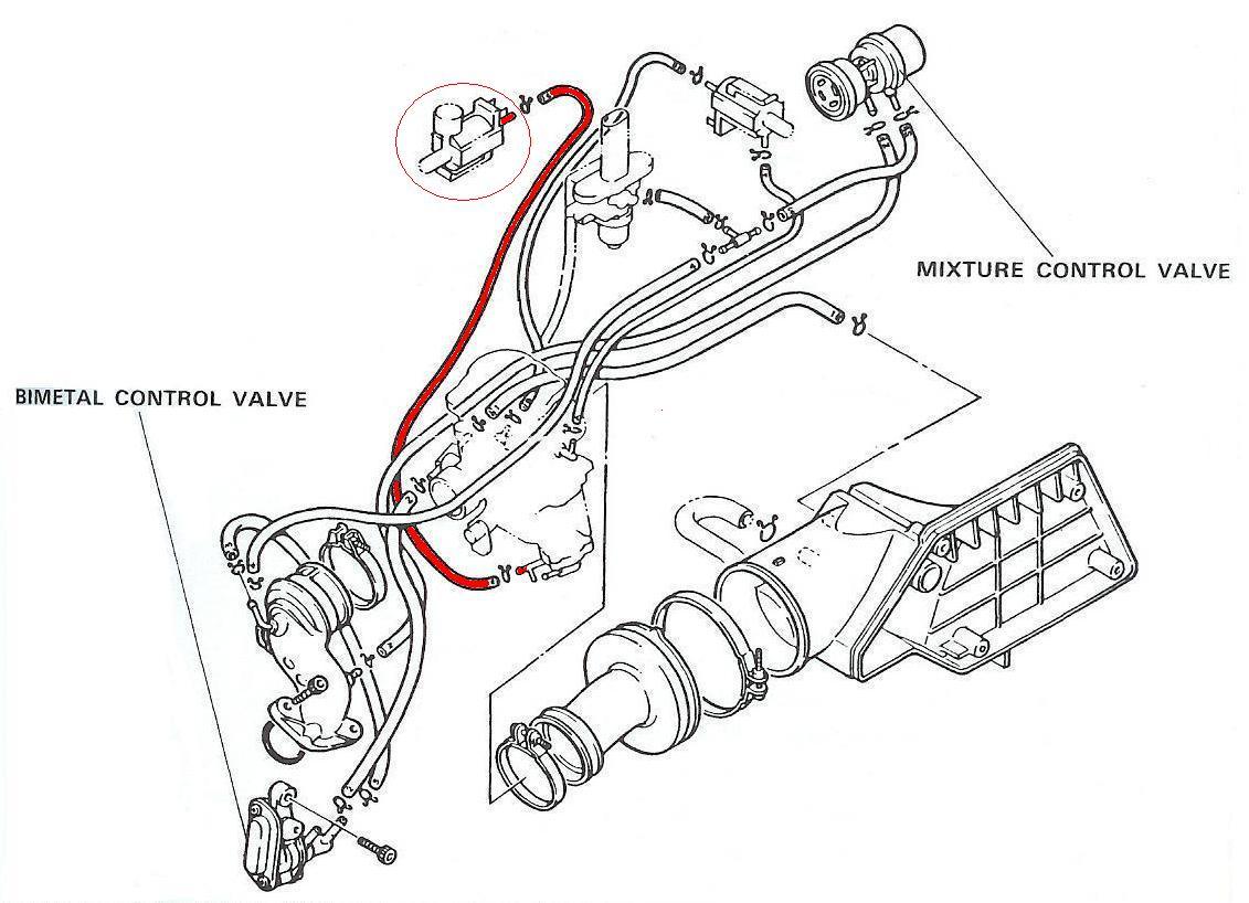
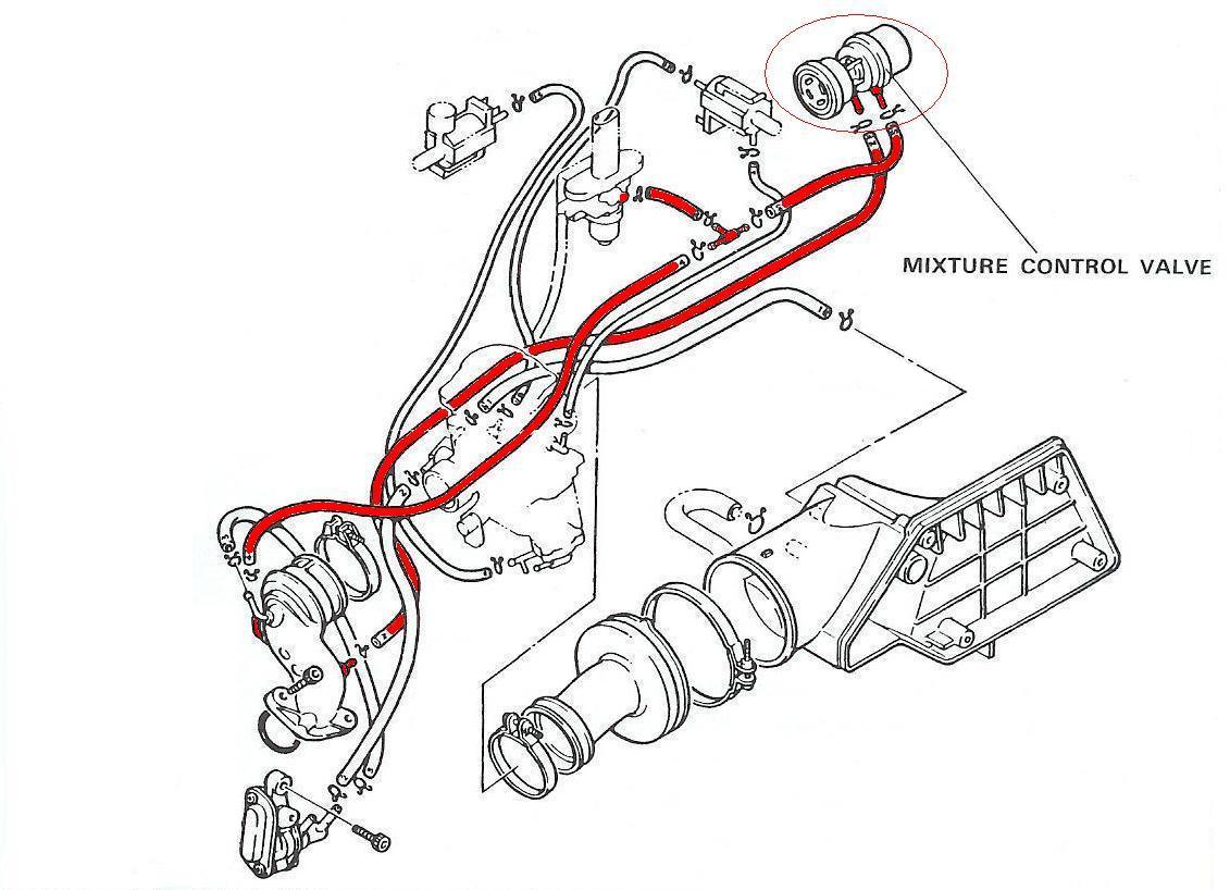
| Mixture control valve Used to prevent too-rich mixtures from occuring when you chop the throttle. Assume you're going at ~5000 rpm and you suddently cut the throttle to coast. This creates a high vacuum in the carb, drawing in lots of fuel and creating a rich mixture. In this situation, the MCV pops open to the atmosphere to lean out the over-rich mixture. It has two vacuum hoses hooked through the carb. MCV hose routing diagram. Here is the SA1 and SA2 diagram. |
 |
| Starting enrichener circuit This is part of a separate starting circuit on the carb. It consists of a plunger, spring, starting jet (covered in detail below), starting air jets (SAJ1 and SAJ2), along with some vacuum connections. The SA solenoid is hooked up to the plunger. The outlet at the very bottom of the plunger assembly is connected to the middle of the carb through a vacuum tube. The connection at the carb is SAJ1. The hole in SAJ 1 is small, and it must be kept clean. Above the plungen outlet is a "T" connector. The straight part of the T is connected to the SA solenoid. The 90 degree part of the T is the SAJ 2 connection, which has a short tube vented to the atmosphere. SAJ 2 has a very small opening, which must be kept clean. Air jet hose routing diagram. SA1 and SA2 diagram. |
 |
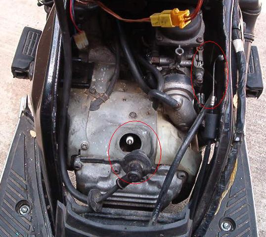
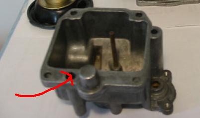
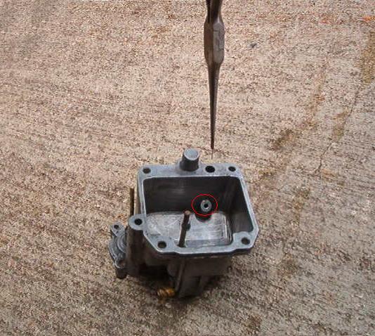
| Starting jet In my experience, this tiny little part is one of the main causes of Riva 180 starting problems. It is part of carb float bowl - it's buried in the rim of the float bowl. Because it's so tiny, it can clog easily. Even a thorough carb cleaning may not clean out this jet. It is best cleaned with a #78 wire bit (0.0145" in diameter). You can also use guitar string or the equivalent. The way to tell if it's clean is to squirt some carb cleaner through a nozzle into the hole at the base of the jet (the red circle in the picture "the rim of the float bowl" noted above). Keep your eyes away - the carb cleaner will squirt everywhere! If the jet is clean, you'll see most of the carb cleaner squirt out the top of the jet (which will go several inches above the float bowl.) |
 |
© Copyright 2003-2011 by Jack Stanley. All Rights Reserved.
|